Mechanical Friction Torque Limiter Mechanisms with Adapters
MECHANICAL FRICTION TORQUE LIMITERS
Mach III friction torque limiters, also known as slip clutches, are designed to transmit a fixed amount of torque from one machine component to another until an overload is experienced. A torque setting is established by compressing the adjustment nut to the desired torque output, then fixing it in place with the provided set screw(s). This can be set and adjusted in the field, or pre-set at Mach III before shipment. When the unit experiences torque in excess of the set value, the friction torque limiter slips until the overload ceases.
IMPORTANT: Mach III friction torque limiters do not disengage upon overload. A means of sensing and stopping the overload condition must be in place or a friction torque limiter will continue to slip, eventually overheating to the point where it is unfit for continued use.
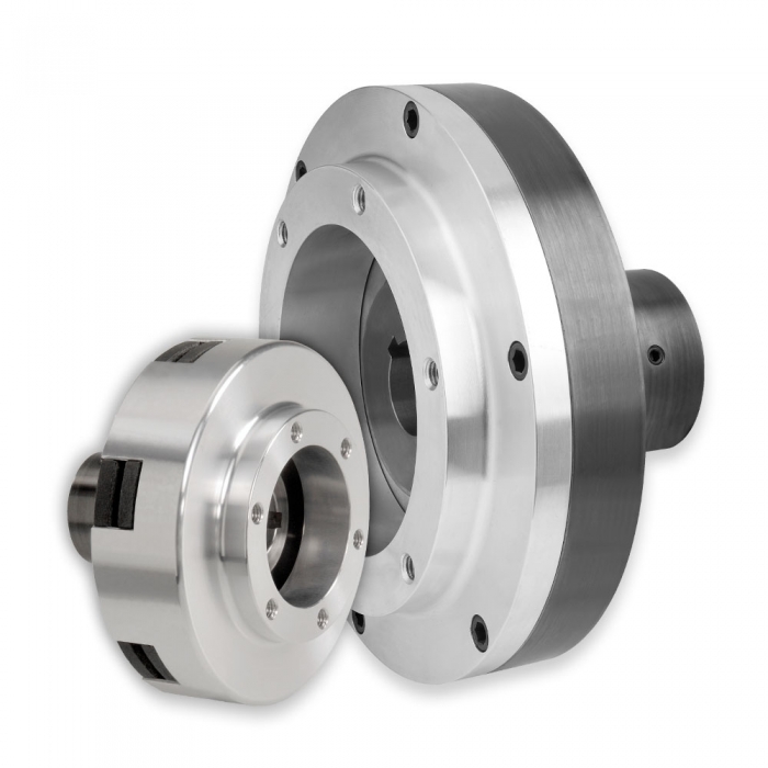
MECHANICAL FRICTION TORQUE LIMITER MECHANISMS WITH ADAPTERS
Continuously Engaged, Momentary Overload Protection
Function: Overload Protection
Drive Arrangement: Shaft to Adapter Mounted Component
Torque limiter mechanism is through bored and keyed to connect to a fully supported shaft.
Adapter connects to a bearing mounted pulley, gear or other component.
Operation
Mechanically adjustable, continuously engaged friction torque limiter slips in the event of an overload.
Torque at which limiter will slip is field adjustable through the tightening or loosening of a nut.
Adjustment nut is locked in place by set screws when desired torque setting is established.
Mounting
Through/Mid Shaft or End of Shaft.
Torque Limiter slides on shaft and is fixed with set screws and customer supplied key.
Adapter connects to a fully supported, bearing mounted pulley, gear, or sprocket.
Note: Mechanism DOES NOT support Adapter.
Applications
Momentary overload protection.
For continuous slip or tension control applications, a SensiFlex® clutch or brake should be used.
Maximum RPM varies by model. Please consult the detail sheets (below). Consult engineering if the intended application exceeds the listed maximum RPM.
Design Features
No reset required.
Bored to suit up to the maximum shown (US & Metric) for easy installation.
Machined face and bolt circle on adapter facilitate connection to bearing mounted pulley or gear.
|
Product Code |
Maximum Recommended Torque Setting |
Maximum Bore with Standard Keyway |
Detail Sheet |
|
V2R2R-STL |
200 lb-in |
0.500 in (12 mm) |
|
|
V3R2H-STL |
792 lb-in |
1.000 in (24 mm) |
|
|
V4R2H-STL |
1,406 lb-in |
1.250 in (31 mm) |
|
|
V5R2H-STL |
2,736 lb-in |
1.438 in (38 mm) |
|
|
V6R1G-STL |
3,070 lb-in |
2.000 in (52 mm) |
|
|
V6R2G-STL |
6,140 lb-in |
2.000 in (52 mm) |
|
|
V8R1K-STL |
6,066 lb-in |
2.500 in (66 mm) |
|
|
V8R2K-STL |
12,132 lb-in |
2.500 in (66 mm) |
Quote Request
If you have any questions regarding the products we are offering, pleasee fill out the form below and one of our representavies will contact your shortly. Thank you for your interest in Drive Line!